Introducing the well
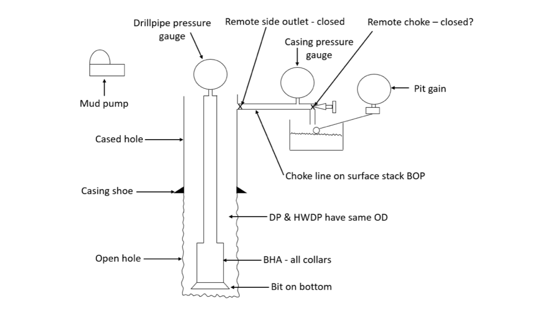
During the class you have built up a good picture of a well that your instructor will use throughout the week to explain various topics as the course progresses. Here is a refresher on some of the key areas but using different well data – don’t want to kill the surprise in class now do we?
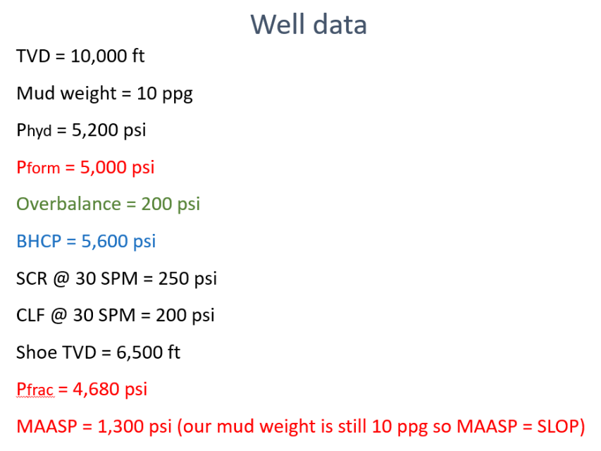
So, if we add some data to the well we get
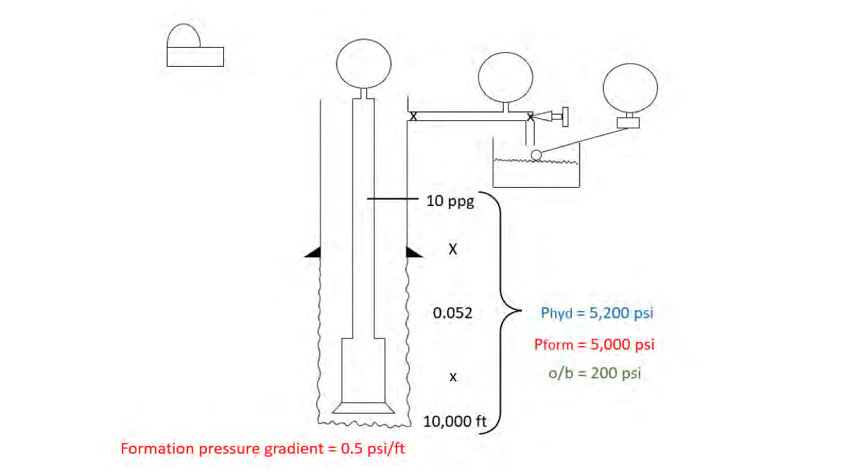
At the moment in our well, bottom hole pressure is the same as hydrostatic pressure – 5,200 psi.
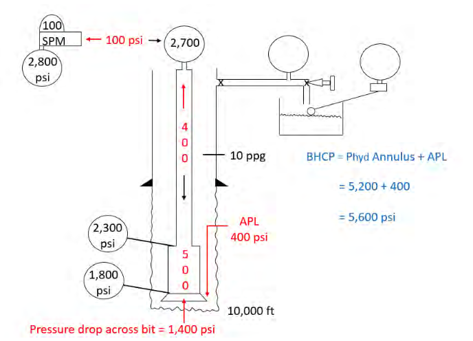
However, at some point we need to turn the pumps on, and we will introduce circulating pressures (caused by friction) into the well. Circulating pressure acts opposite to the direction of travel meaning we can see the total amount of friction in the system on the pressure gauge on the rig pump.
We can see all the friction in the well caused by circulation on the standpipe pressure gauge on the rig floor because remember all circulating pressure acts opposite to the direction of travel. Only one of the system circulating pressures acts onto the bottom of the hole and that is the pressure loss in the annulus or APL for short.
When the pumps are running bottom hole pressure increases from simply being equal hydrostatic pressure to hydrostatic pressure plus APL.
Using PDC we can convert bottom hole circulating pressure to an equivalent mud weight using BHCP and 10,000 ft. This equivalent mud weight is known as ECD.
ECD can also be calculated using IWCF formula 7 – try it and see what you get for this well.
We have two formulas on the IWCF formula sheet that can help us work out what happens to circulating pressure if we change either our pump speed or our mud weight. Those are formulas 9 & 10 and remember you can flip them round to make them calculator friendly thus:
and
When you slow your pumps down all circulating system pressures go down including APL. If we slowed the pumps to 30 spm from 100 spm what will the new APL be? From our example above APL is 400 psi at 100 spm.
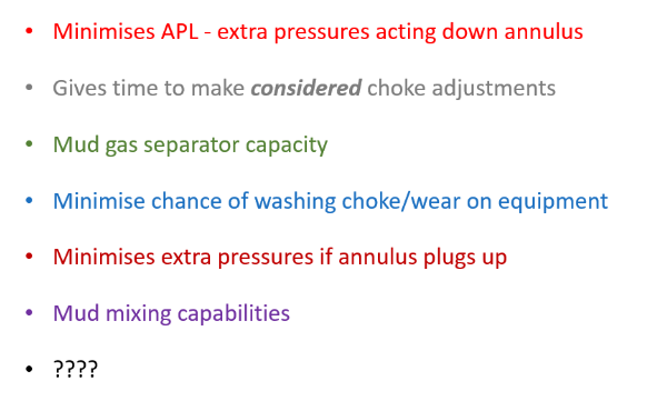
We kill well at slow pump speeds and thirty strokes per minute is a very common kill rate. By killing at a slow rate we minimise APL as seen above. Other reasons for killing wells at slow pump rates are:
We regularly measure the circulating pressure at kill rate so we have an approximate idea what our likely circulating pressure will be during a kill operation, and we tend to call these values our SCR’s. We are lined up for normal drilling operations when we measure SCR’s – the well is open, and we circulate down the string and back up the annulus through an open BOP to the flow line.
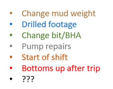
SCR pressure readings should be measured at the drill pipe pressure gauge on the remote choke panel. Why? SCRs are commonly taken:
For the well in this book we are going to say that at 30 spm our SCR was 250 psi (try formula 9 using standpipe pressure from earlier and see what you get).
APL at kill rate is often such a small value that for planning purposes it can be ignored and given we only have 36 psi of APL in our 10,000 ft well we will ignore it. Real world it could be significant and therefore might have to be taken into consideration when planning well control operations.
When using subsea BOP stacks we will be circulating up through a small diameter choke line during a kill operation and the extra circulating pressure in the choke line (choke line friction or CLF) may not be such a small value that it can be ignored. To that end we need to measure it and there are a few ways we could do that.
We could circulate down the string, back up the annulus to a closed BOP then up the choke line through a full open choke. The circulating pressure going this way will be higher than the SCR circulating pressure when the well was open. The difference is choke line friction.

We could circulate the same route but measure the pressure directly off the kill line gauge by opening the failsafe valves on the kill line.
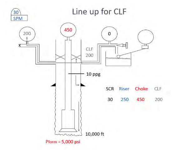
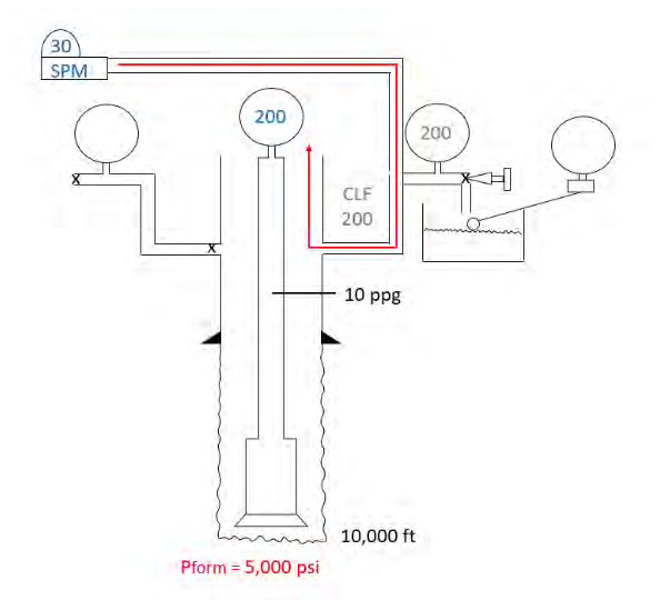
We could pump down the choke line and up the riser and not only measure CLF but flush our choke line at the same time. We should flush the kill line every shift also.
Finally, we could isolate both the riser and the well by closing BOP’s and circulate down the kill line and up the choke line – CLF will be half the reading on the gauge.

This final method is more theoretical than anything else because with the lower rams closed, we are no longer able to monitor the well and we should always monitor the well if we can.
The last bit of information that we now need about our well is what kind of formation strength do we have. Formation strength usually increases with depth. As you drill deeper there is more overburden which contributes to the overall strength of the formation.
The closer you are to surface the weaker your formation usually is therefore we assume the open hole just after your last casing shoe is the weakest part of the well. For simplicity we say the shoe is the weakest part of the well and therefore it is important to establish what the formation strength at the shoe is.
To this end we conduct a strength test just after we have drilled out the shoe, rat hole and up to fifteen feet of new formation. There are two tests we could perform – a formation integrity test (FIT) which checks the formation can withstand a pre-calculated value; or a leak off test (LOT) which establishes what the formation strength is.
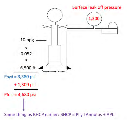
With an LOT you pump slowly into the well, measuring how much fluid you pump in, and when you see the pressure start to break away from a straight line this is your surface leak off pressure (SLOP). When you bleed the pressure off you should get the same volume of fluid back from the well. Your shoe fracture pressure (or breakdown pressure or formation strength) is the sum of the hydrostatic pressure acting on the shoe plus the SLOP.
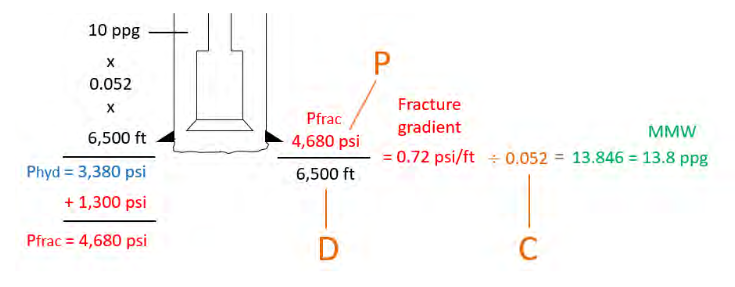
Once we know fracture pressure and shoe TVD we can PDC it to work out maximum mud weight.
Maximum mud weight can also be worked out using formula 11 on the IWCF formula sheet:
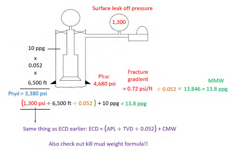
As mentioned above formula 11 does the same thing as formula 7 and also formulas 8 & 13 - PDC inside the brackets plus a mud weight – it’s the same well control again and again and again – honest!
Once you have maximum mud weight you can work out MAASP (Maximum Allowable Annular Surface Pressure) which is the maximum pressure that can be applied to the shoe at surface, over and above the mud hydrostatic pressure acting on the shoe, before you risk damaging the formation at the shoe. SLOP is first MAASP or MAASP for test mud.
Because MAASP is affected by hydrostatic pressure you need to recalculate MAASP every time you change your mud weight. There are a few ways to work out MAASP but let’s keep it simple and use the MAASP formula (number 12 on the formula sheet and on the kill sheet of which more later). Using our well above what will MAASP be if the mud weight is increased to ?
When you increase your mud weight MAASP decreases.
If you look at the MAASP formula it is a hydrostatic calculation –
OK we now have a pretty good picture of the well – time to get ourselves into a bit of bother but first here’s a summary of what we know so far: